
Loudness Threshold as a Function of Sound Source Location Using Circum-Aural Headphones in Noisy and Sound-Proof Acoustic Environments
Project Overview
SCIENTIFIC PROJECT MEMORANDUM: PSYCHOACOUSTIC PERFORMANCE REPORT
I. OBJECTIVE AND HYPOTHESIS
1. Statement of the Problem
The vast majority of modern consumer circum-aural and intra-aural headphones either physically deform the pinna (external ear) or bypass its structural geometry completely by routing sound directly into the auditory canal. This physical configuration nullifies the natural, direction-dependent spectral wave-filtering and spatial acoustic amplification capabilities inherent to the anatomy of the human external ear.
2. Research Objective
To isolate and exploit these natural anatomical advantages, a customized circum-aural headphone assembly was engineered. This apparatus encompasses the entire external ear without inducing mechanical deformation. Internal acoustic drivers were structurally positioned to project sound waves onto specific, direction-dependent anatomical sites of the pinna.
3. Experimental Hypothesis
It was hypothesized that directing sound wave fronts toward these precise anatomical landmarks would engage the natural high-frequency transfer functions of the pinna (4 kHz - 12 kHz), thereby yielding heightened auditory sensitivity—quantified as significantly lower hearing thresholds—within that specific spectral band.
II. EXPERIMENTAL METHODOLOGY AND DESIGN
1. Hardware Modification
The experimental apparatus was constructed by modifying a commercial control headset (SONY MDR-NC7/WHI). The modified experimental architecture repositioned the acoustic drivers approximately 1 - 2 cm from the entrance of the auditory canal at an elevation angle of 20°. A rigid plastic strip measuring 40 × 30 × 1 mm was mounted at a 10° angle to establish a fixed azimuth guide, focusing the target wave fronts directly toward the upper canal architecture.
2. Environmental Conditions
A cohort of 43 undergraduate participants was evaluated across two distinct acoustic environments:
3. Psychophysical Task and Calibration
Auditory thresholds were mapped across 29 discrete frequencies spanning 40 Hz to 20 kHz. Stimuli were deployed via a custom MATLAB graphical user interface utilizing a 3 dB step-down automated decrement protocol. To control for confounding variables arising from idiosyncratic anatomical variations and hardware frequency response fluctuations, an intrinsic baseline calibration was implemented. A 3500 Hz reference tone was established independently for each participant-headset pairing to serve as a normalized, intrinsic 0 dB reference threshold baseline.
III. DATA ANALYSIS AND KEY FINDINGS
1. High-Frequency Sensitivity Enhancement
Empirical data validated the structural design parameters. The customized experimental headphones demonstrated a statistically significant performance advantage over the standard commercial layout in the high-frequency spectrum (4 kHz - 12 kHz), recording markedly lower detection thresholds.
2. Low-Frequency Attenuation Trade-off
Conversely, the experimental positioning introduced a distinct acoustic trade-off. The altered driver placement resulted in elevated detection thresholds (diminished sensitivity) across the lower-frequency bands when compared directly to the control hardware.
3. Ambient Noise Interaction and Stimulus Saliency
Crucially, the heightened high-frequency sensitivity provided by the custom architecture was not attenuated by the introduction of environmental noise. Within the ambient noise condition, the experimental headphones required significantly less signal amplification to reach detection thresholds in the 4 kHz - 12 kHz band than what was observed in the soundproof condition.
Because the background laboratory noise was concentrated in the lower spectral frequencies and the experimental stimuli were physically aligned with the pinna’s natural amplification pathways, the target high-frequency signals achieved an elevated degree of sensory contrast. This phenomenon is analogous to the high visual saliency observed when viewing a single white target within a dark or uniform field.
Product Architecture: (3D structure based and Physical calibration)
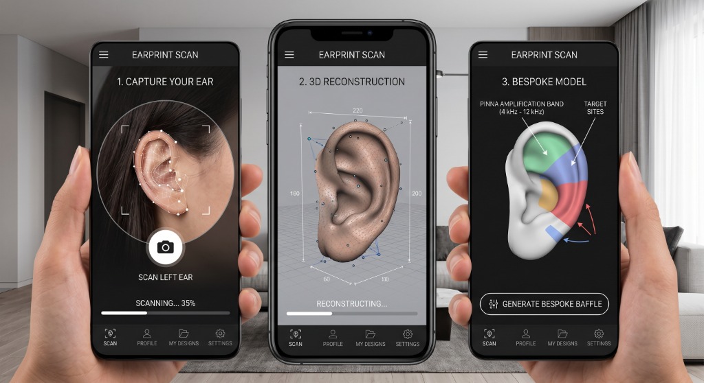
1. Digital Pre-Calibration (3D Photogrammetry)
The Interface: The user initiates a lateral cranial scan via a dedicated smartphone application. The software captures a high-density geometric mesh mapping the concha volume, tragus, and helix architecture.
The Baffle Assembly: An automated cloud algorithm extracts individual coordinate vectors and exports a parametric CAD model for the headphone's internal baffle plate. The internal component is manufactured via high-resolution selective laser sintering (SLS) using a dense, non-resonant acoustic polymer. This ensures that the high-frequency driver pod is structurally anchored at the user's computed biological baseline.
2. Physical Calibration (Mechanical Micro-Gimbal Matrix)
To account for headphone slippage, cushion decompression, or micro-anatomical adjustments, the internal high-frequency tweeter is decoupled from the main housing and suspended on a constrained, two-axis ball-and-socket micro-gimbal. The user manipulates this matrix externally via a dual-concentric dial mechanism:
IV. Mechanical Engineering & Tolerancing Specs
To prevent chaotic internal reflections, acoustic bleeding, and cheap tactile play, the mechanical assembly is governed by strict geometric limits.
1. Fit, Friction, and Damping
2. Acoustic Architecture Specifications
Specifications
Tech Stack
Need help in research integration?
Get in touch to discuss specialized development and consulting opportunities.